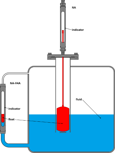
The float level indicator NA consists of a display part, a pipe and a float which are installed in the tank. The float is permanently connected via a connecting rod to the magnet holder in the display part. When the level in the tank rises, the float and the rod are forced upwards by the buoyancy force, and the filling level can be read from the display.
The level indicator NA-V4A operates on the principle of communicating vessels, and is mounted outside the tank. It is connected to the tank via a feed pipe and an overflow. When the filling level in the tank rises, it also rises in the measuring tube.
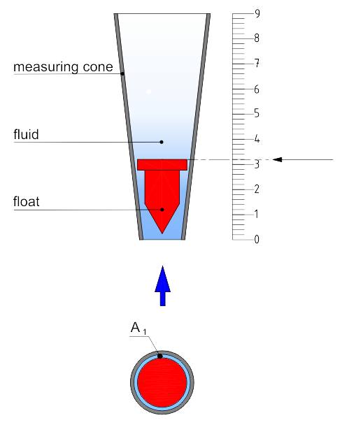 The float can easily move up and down in the conical measuring tube.
The vertical position of the float, obtained as a function of the flow velocity of the measuring media, is an indication of the flow rate.
This flow rate can be read directly on the scale of the measuring tube.
With increasing volume flow, the annular gap surface area A around the collar of the float increases (A2 > A1).
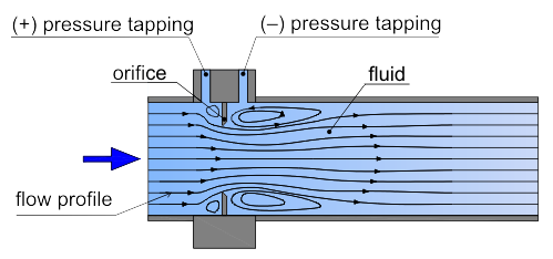
A differential pressure arises at a pipe constriction, which is proportional to the square of the flow rate through the pipe.The resulting differential pressure can be recorded with a meter and can be directly indicated as flow rate on a scale.
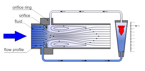
The bypass flow meter operates on the differential-pressure-bypass method. A ring with an orifice plate is installed in the pipeline between flanges. The measuring orifice leads to a constriction and causes a differential pressure. As compensation a volume flow occurs in the bypass which is displayed by a variable area flow meter. This partial flow is proportional to the flow rate in the main pipeline.The unimpeded, straight tube length has to be 6DN before and 4 DN behind the mounting position. The partial flow can be turned on and off, as required, by installing two ball valves in the bypass line..
 Hazardous areas are defined are areas with a risk of explosion caused by flammable gases, combustible vapours, dust or fibre.
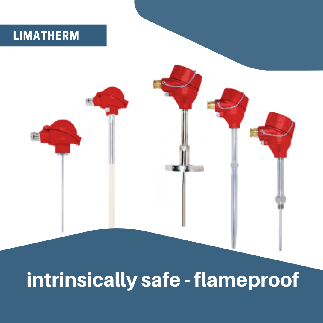
The term explosion proof protection means that the enclosure (housing) contains the ignition and explosion. The housing material is usually made from cast iron or aluminum. Explosion proof is often used synonymously to flameproof.
Intrinsically safe means that the electronics or wiring are constructed in a way that they limit the energy in the circuit in order to prevent sparks causing ignition. Read more on classes, zones and areas.
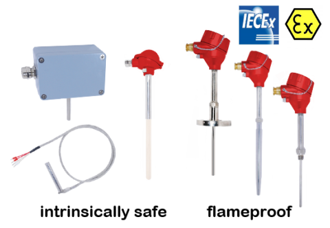 Solutions and warranty claims for hazardous areas require the testing and certification of the complete temperature unit (sensor and housing) and not just the individual components.
Limatherm offers certified temperature solutions for complete temperature units in flammable/explosion proof and intrinsically safe areas.